
Views: 0 Author: Site Editor Publish Time: 2026-09-30 Origin: Site


In continuous process plants, measurement precision directly dictates operational safety, product yield, and system uptime. Specifying the wrong pressure measurement instrument leads to accelerated sensor degradation, calibration drift, process contamination, or catastrophic failure during pressure spikes. Plant operators cannot rely on baseline specifications alone. Moving beyond basic data sheets requires evaluating transmitters through the lens of exact process media, environmental extremes, and long-term lifecycle stability. This guide breaks down the technical criteria for selecting the correct transmitter architecture for specific plant applications. We will examine how to match sensor types to field realities, ensuring reliable asset management in harsh industrial environments without over-specifying unnecessary features.
Measurement type dictates the instrument: Selecting between gauge, absolute, and differential pressure is the foundational step for accurate process variable monitoring (pressure, level, or flow).
Media dictates the mechanical interface: Viscous, crystallizing, or sanitary media require specific physical profiles to prevent clogging and contamination.
Environmental extremes demand specialized builds: Standard sensors fail rapidly under thermal shock or severe hydraulic cycling; specialized high-temperature or high-cycle variants are non-negotiable for these environments.
Digital integration drives predictive maintenance: Modern digital protocols (HART, IO-Link, Profibus) and advanced diagnostics transform passive measurement devices into active tools for plant-wide asset management.
Selecting the right instrumentation starts with understanding the foundational mechanics of your process. Every application demands a specific measurement typology. Gauge pressure transmitters measure relative to ambient atmospheric pressure. You use these for open-tank level measurements, pump discharge monitoring, and standard pipe pressure tracking. Absolute pressure transmitters measure relative to a perfect vacuum. These are mandatory for distillation columns, vacuum reactors, and processes where atmospheric pressure fluctuations would corrupt the data. Differential pressure (DP) transmitters measure the drop across a primary element. DP units serve as the backbone of flow rate calculations and pressurized vessel level monitoring.
Process engineers frequently debate accuracy versus reliability. Laboratory-grade accuracy looks excellent on a specification sheet. However, field reliability matters more in harsh industrial environments. Repeatability, resolution, and long-term stability outweigh absolute accuracy when dealing with heavy vibration, temperature swings, and mechanical stress. A highly accurate sensor that drifts after one month of thermal cycling offers less value than a slightly less accurate sensor that holds its calibration for five years under continuous load.
Regulatory and safety compliance strictly governs instrument selection. You must match transmitter specifications to plant safety frameworks. Safety Integrity Level (SIL 2 or SIL 3) ratings dictate the reliability of instruments tied to safety instrumented systems (SIS). These ratings rely on calculated Failure in Time (FIT) rates and often require redundant voting architectures like 1oo2 or 2oo3 setups. Sour gas environments require NACE MR0175 or MR0103 compliance to prevent sulfide stress cracking in wetted materials. Hazardous areas demand specific installation methods. Intrinsically Safe (IS) designs limit electrical energy to prevent ignition. Explosion-Proof (Ex d) housings contain any internal explosion, preventing it from igniting the surrounding atmosphere. You must match these certifications to your specific ATEX or IECEx zone classifications.
Process media profiling forms the final baseline criterion. You must analyze the fluid or gas contacting the sensor. Assess corrosiveness to determine if standard stainless steel suffices or if exotic alloys are necessary. Evaluate viscosity and specific gravity to calculate flow or level accurately. High particulate content or crystallizing media dictates the mechanical interface, often requiring specialized diaphragm configurations to prevent clogging and ensure continuous measurement.
General-purpose transmitters handle baseline gas, liquid, and vapor measurement. These units typically feature a threaded process connection (such as 1/2 NPT) and a piezoresistive or capacitive internal sensor. You will find standard units deployed across cooling water systems, compressed air lines, and baseline chemical dosing skids. They provide reliable data for utility monitoring and non-critical process loops where conditions remain relatively stable.
However, standard units have strict physical limitations. They cannot survive extreme temperatures, highly aggressive chemicals, or heavy particulate loads. Deploying a standard industrial pressure transmitter in a highly viscous application inevitably leads to plugged impulse lines and failed readings. Recognizing these limitations prevents premature instrument failure and keeps maintenance teams focused on actual plant optimization rather than constant sensor replacement.
DP transmitters execute complex calculations beyond simple pressure monitoring. When paired with orifice plates, pitot tubes, or venturi tubes, DP transmitters calculate volumetric and mass flow rates. The pressure drop across the primary element correlates directly to flow velocity. In pressurized vessels, DP transmitters calculate hydrostatic liquid levels by comparing the high-pressure liquid head against the low-pressure vapor space. This requires careful consideration of wet leg versus dry leg installations depending on whether the vapor condenses.
Modern DP installations utilize coplanar designs. Coplanar architectures reduce weight, minimize leak points, and simplify manifold integration. Multivariable transmitters take this further. They measure differential pressure, static pressure, and process temperature simultaneously. This allows the transmitter to compensate for density changes dynamically, delivering highly accurate mass flow data from a single penetration point and reducing the overall number of required pipe taps.
Fluid power systems and heavy machinery destroy standard sensors rapidly. High-vibration environments and severe pressure spikes require a dedicated hydraulic pressure transmitter. These units feature robust structural differences. They utilize thick-film or thin-film sensor technology fused directly to a solid steel diaphragm, eliminating fluid-filled cavities that can rupture under mechanical stress.
Robust snubber integration is mandatory for these applications. Snubbers dampen instantaneous pressure spikes and water hammer effects before they reach the sensing element. This prevents zero-shift and permanent diaphragm deformation. Primary plant applications include hydraulic presses, heavy lifting equipment, blowout preventers (BOPs), and high-pressure injection systems. These environments demand high-cycle fatigue resistance to survive millions of rapid pressure actuations without signal degradation.
Extreme heat destroys sensitive sensor electronics and degrades standard fill fluids. A high temperature pressure transmitter isolates the delicate circuitry from the process media. Engineering solutions include integrated cooling fins, capillary lines, and remote diaphragm seals. Remote seals utilize specialized fill fluids like Syltherm, high-temperature silicone oils, or even NaK (sodium-potassium) alloys to transmit pressure mechanically while keeping the transmitter housing in a cooler ambient zone.
Typical deployment scenarios include steam generation plants, exothermic chemical reactors, and high-temperature distillation columns. Thermal gradients heavily impact measurement accuracy. As fill fluids heat up, they expand, creating artificial pressure on the sensor. Advanced transmitters calculate and compensate for these temperature error bands dynamically, ensuring the output signal remains accurate despite fluctuating process heat.
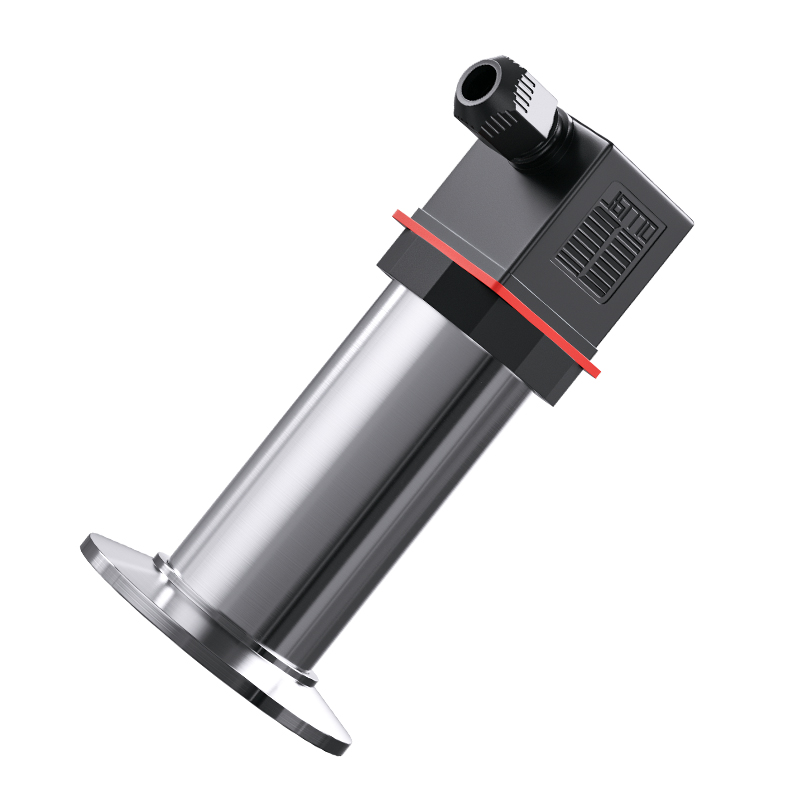
Viscous and crystallizing media plug standard threaded connections instantly. A flush diaphragm pressure transmitter solves this by placing the sensing diaphragm completely flush with the process wall. This mechanical design eliminates dead legs, hidden cavities, and impulse lines where media can stagnate, harden, or breed bacteria.
Critical use cases span multiple industries. Food and beverage processing relies on flush designs with Tri-Clamp connections for Clean-in-Place (CIP) and Steam-in-Place (SIP) compliance. Pharmaceutical manufacturing requires them to meet EHEDG standards and prevent batch-to-batch contamination. Pulp and paper processing, along with wastewater treatment, utilizes flush sensors to handle heavy slurries. Operators can clean the pipes mechanically without removing the instrumentation, avoiding plugged connections and unexpected downtime.
The internal sensing mechanism dictates how the instrument behaves under stress. You must map the technology to the specific plant environment based on overpressure tolerance, burst ratings, and vibration resistance.
Sensor Technology | Core Characteristics | Optimal Plant Environment |
|---|---|---|
Piezoresistive | High sensitivity, fluid-filled isolation, excellent linearity across broad ranges. | General purpose gas and liquid processing, chemical dosing, standard utility lines. |
Capacitive | Exceptional overpressure tolerance, highly sensitive to minute pressure changes. | Low pressure/draft ranges, level measurement, applications prone to pressure surges. |
Thin-film | No internal fill fluid, extreme durability, high burst pressure ratings. | High-pressure hydraulic systems, heavy machinery, high-vibration compressor skids. |
Turndown ratio defines the operational flexibility of the transmitter. It represents the ratio between the maximum measurable pressure (Upper Range Limit) and the minimum calibrated span. A transmitter with a 100:1 turndown ratio offers massive inventory management advantages. Plant managers can stock one transmitter model and configure it for multiple pressure ranges across different units, drastically reducing spare parts inventory.
However, extreme turndown ratios come with performance trade-offs. While a 100:1 ratio is electronically possible, pushing a sensor to its extreme lower limits degrades actual measurement accuracy. The signal-to-noise ratio drops significantly. For example, a transmitter calibrated for 0-1000 psi re-ranged to 0-10 psi will likely see ambient temperature effects exceed the actual measured value. For critical control loops, operating closer to a 10:1 or 20:1 turndown ensures optimal resolution and stability.
Legacy analog outputs (4-20mA, 0-10V) remain standard for basic control and often incorporate NAMUR NE43 fault signaling to indicate sensor failure. However, digital communication protocols like HART, Foundation Fieldbus, Profibus PA, and IO-Link dominate modern process plants. Digital integration allows two-way communication, enabling remote configuration and continuous health monitoring from the control room.
WirelessHART and ISA100 protocols see growing adoption for remote or hard-to-reach measurement points. They eliminate the massive infrastructure requirements of running new conduit and wiring across sprawling facilities. Digital integration also unlocks advanced diagnostics. Modern transmitters feature Plugged Impulse Line (PIL) detection, alerting operators before a blockage causes a process upset. They also report secondary variables, such as ambient sensor temperature, streamlining commissioning and troubleshooting via DCS or PLC systems.
Focusing solely on initial procurement often leads to higher long-term maintenance burdens. Lower-tier transmitters frequently suffer from accelerated drift, requiring constant recalibration. Unplanned downtime and the labor hours spent troubleshooting unreliable instruments quickly outpace any initial savings. Evaluating lifecycle maintenance requires looking at modularity. Premium transmitters often feature replaceable sensor modules. If a diaphragm ruptures, maintenance teams replace the sensor capsule rather than discarding the entire transmitter housing and electronics.
Calibration drift is inevitable, but the rate of drift varies wildly based on sensor quality. Mechanical stress, extreme temperature cycling, and minor overpressure events cause the zero and span points to shift. In harsh industrial environments, standard sensors may require a full 5-point recalibration every six months to maintain process tolerances.
Investing in premium sensors with guaranteed long-term stability transforms maintenance schedules. Sensors rated for less than 0.1% URL drift over 5 to 10 years allow instrumentation technicians to extend calibration intervals safely. This reduces hands-on maintenance hours, minimizes process interruptions, and ensures control loops remain tightly optimized without constant human intervention.
Wetted material selection directly dictates the Mean Time Between Failures (MTBF). Standard 316L Stainless Steel handles most water, air, and mild chemical applications. However, deploying 316L in aggressive environments guarantees rapid failure.
Wetted Material | Primary Resistance Profile | Typical Plant Application |
|---|---|---|
316L Stainless Steel | General corrosion resistance, baseline durability. | Water, compressed air, mild hydrocarbons, non-corrosive gases. |
Hastelloy C-276 | Excellent resistance to pitting, stress corrosion cracking, and oxidizing atmospheres. | Sour gas (H2S), chlorine gas, sulfuric acid processing. |
Monel 400 | High resistance to hydrofluoric acid and seawater. | Alkylation units in refineries, offshore platform processes. |
Tantalum | Near-universal chemical inertness, similar to glass. | Highly concentrated boiling acids, aggressive pharmaceutical batches. |
Gold-Plated | Blocks hydrogen ions from penetrating the metal lattice. | Refinery processes prone to hydrogen permeation and sensor embrittlement. |
Instantaneous overpressure events destroy sensing diaphragms. Water hammer in liquid lines or sudden valve closures can generate pressure spikes ten times the normal operating range. This permanently shifts the zero point or ruptures the sensor entirely.
Mitigate this risk by specifying transmitters with high overpressure ratings. Install physical snubbers or pulsation dampeners immediately upstream of the transmitter. In steam applications, always utilize loop-pigtail siphons. The siphon traps condensate, ensuring that live, high-temperature steam never makes direct contact with the sensitive transmitter diaphragm.
Radiant heat or sudden media temperature changes cause electronic failure, fill-fluid vaporization, and severe measurement drift. If the process fluid exceeds the sensor's limits, the internal fill fluid boils, destroying the instrument.
Implement remote diaphragm seals with appropriate high-temperature fill fluids to isolate the electronics. Use stand-off pipes to dissipate heat before it reaches the transmitter body. Always verify the ambient temperature limits of the transmitter housing. In extremely hot environments, you may need to mount the transmitter remotely and connect it via capillary tubes to keep the electronics in a safe thermal zone.
Process media solidifying, freezing, or building up in impulse lines causes a complete loss of measurement or dangerously false readings. A plugged line traps pressure, telling the DCS that the system is stable even if the actual pipe pressure is dropping rapidly.
Utilize steam tracing or electrical heat tracing alongside winterization enclosures for cold-weather deployments to prevent freezing. For heavy particulate media, implement continuous purge systems that constantly blow clean fluid or gas back through the impulse lines. The most effective mitigation for plugging is switching to a flush diaphragm design, completely eliminating the vulnerable impulse line.
Poor mechanical and electrical installation guarantees false readings, delayed response times, and EMI interference. Improperly routed impulse lines trap gas in liquid applications or trap liquid in gas applications, corrupting the pressure signal.
Establish strict routing guidelines. Liquid lines must slope downward to the transmitter at a minimum ratio of 1 inch per foot, while gas lines must slope upward. Select the correct manifold: use 2-valve manifolds for gauge and absolute transmitters, and 3-valve or 5-valve manifolds for DP transmitters to allow safe equalization and calibration without interrupting the process. Finally, enforce correct grounding and shielding practices to protect the low-voltage analog or digital signals from plant floor electrical noise.
Audit current high-failure measurement points across the plant to identify misapplied standard sensors that require specialized replacements.
Consult a process instrumentation engineer regarding hazardous area compliance and SIL ratings before executing any upcoming SIS upgrades.
Request evaluation units and run pilot tests in your harshest plant conditions before standardizing on a new transmitter architecture.
Update maintenance protocols to include regular visual inspections of impulse lines, manifolds, and heat tracing systems prior to winter operations.
A: Gauge transmitters measure pressure relative to ambient atmospheric pressure. Absolute transmitters measure relative to a perfect vacuum, ignoring atmospheric changes. Differential pressure (DP) transmitters measure the difference between two distinct pressure points, commonly used for calculating flow rates or tank levels.
A: You must use a flush diaphragm when measuring highly viscous, crystallizing, or slurry-heavy media. Standard threaded connections create dead legs where these materials accumulate and harden, plugging the sensor. Flush designs keep the sensing face clean and allow for mechanical pipe cleaning.
A: Protect the electronics by physically separating them from the heat source. Use remote diaphragm seals connected via capillary lines filled with high-temperature fluids like Syltherm. Alternatively, use stand-off pipes (siphons) to dissipate heat or integrate cooling fins directly into the transmitter housing.
A: Standard transmitters often use fluid-filled piezoresistive sensors suitable for steady processes. Hydraulic transmitters utilize thick-film or thin-film sensors fused to a solid steel diaphragm without internal fill fluids. This solid-state construction withstands extreme vibration, high-cycle fatigue, and severe water hammer.
A: Turndown ratio is the ratio of the transmitter's maximum measurable pressure to its minimum calibrated span. A high turndown ratio allows you to use a single transmitter model across multiple different pressure ranges in the plant, significantly reducing the need to stock various spare parts.
A: Match the material to the specific chemical and temperature profile. Standard 316L stainless steel handles mild media. Use Hastelloy C-276 for pitting resistance, Monel for hydrofluoric acid, and Tantalum for boiling acids. Use gold-plated diaphragms if hydrogen permeation is a known risk in your process.


