
Views: 0 Author: Site Editor Publish Time: 2026-10-07 Origin: Site


Accurate analog signal transmission forms the backbone of industrial process control. Plants rely heavily on the robust 4-20mA current loop standard to communicate process variables from the field to the control room. Mismatches between transmitter power requirements and Programmable Logic Controller (PLC) analog input configurations frequently result in signal degradation, ground loops, blown I/O fuses, or catastrophic module failure. Successfully integrating a 4-20mA pressure transmitter requires a precise evaluation of wiring topologies, loop power constraints, and PLC scaling logic. This guide details the technical requirements for specifying, wiring, testing, and troubleshooting pressure transmitters in industrial control panels. We cover practical field execution, from landing wires on terminal blocks to configuring the A/D converter logic.
Topology Matching: Selecting between 2-wire (loop-powered), 3-wire, and 4-wire (externally powered) configurations dictates the power supply architecture and PLC I/O card selection.
Impedance and Load: Total loop resistance—including cable length, PLC input impedance, and barrier devices—must not exceed the transmitter’s maximum load capacity at the specified supply voltage.
Grounding and Isolation: Proper shield termination and the use of isolated analog inputs are non-negotiable for mitigating electromagnetic interference (EMI) and preventing ground loops in industrial environments.
Fault Detection: The 4-20mA standard inherently supports wire-break detection (0mA), requiring explicit PLC logic to trigger alarms for out-of-range signals.
Plant floors generate massive electromagnetic interference (EMI) from variable frequency drives, large motors, and heavy contactors. When transmitting analog data over long distances, current loops offer distinct technical superiority over voltage signals like 0-10V. Voltage signals suffer from voltage drop across long cable runs due to wire resistance. If you send 10V from a sensor 500 feet away, the PLC might only receive 9.5V, resulting in a massive measurement error.
Current loops eliminate this problem. According to Kirchhoff's Current Law, the current in a closed series circuit is identical at every point. If the transmitter regulates the line to 12mA, exactly 12mA arrives at the PLC analog input card, regardless of cable length or moderate wire resistance. Current loops resist induced electrical noise, making them the default standard for rugged industrial applications.
Feature | 4-20mA Current Loop | 0-10V Voltage Signal |
|---|---|---|
Distance Capability | Excellent (Up to thousands of feet) | Poor (Typically under 50 feet) |
Noise Immunity | High (Current resists induced voltage noise) | Low (Highly susceptible to EMI/RFI) |
Fault Detection | Inherent (0mA indicates a broken wire) | None (0V could mean zero pressure or a cut wire) |
Wiring Complexity | Low (Often requires only 2 wires) | Moderate (Requires 3 or 4 wires) |
The 4-20mA standard utilizes a "live zero" configuration. The baseline signal representing the lowest measurement value (e.g., 0 PSI) is 4mA, not 0mA. This provides immediate, inherent fault detection for control systems.
If a cable is severed, a fuse blows, or the power supply fails, the current drops to 0mA. Because 4mA is the legitimate zero-pressure reading, the PLC easily distinguishes between a system sitting at zero pressure and a hardware failure. You program the PLC to trigger an immediate alarm if the signal falls below 3.8mA. This ensures operators never mistake a dead sensor for a safe, unpressurized pipe.
A functional 4-20mA loop requires four interacting components working in series. A DC power supply (typically 24VDC) provides the driving voltage for the entire circuit. Industrial power supplies should feature low ripple voltage to prevent signal fluctuation. The transmitter acts as an active current regulator, modulating the current flow between 4mA and 20mA based on the physical pressure applied to its diaphragm.
The receiver is the PLC analog input module. This module contains a precision internal resistor, frequently 250 ohms. As the 4-20mA current flows through this resistor, it creates a 1-5VDC voltage drop. The PLC's analog-to-digital (A/D) converter reads this voltage and translates it into a digital integer. Field wiring connects these components, introducing parasitic resistance that you must account for during panel design.
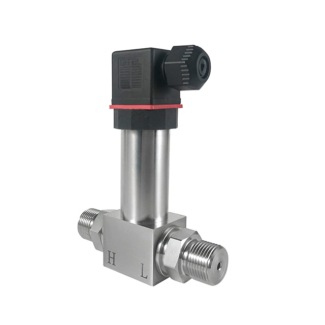
The most common configuration in process automation is the 4-20mA two-wire pressure transmitter. In this architecture, the same two wires provide the 24VDC power to operate the sensor electronics and carry the 4-20mA return signal back to the control panel.
This setup minimizes cabling costs and simplifies conduit runs. You only pull a single twisted pair to connect the field device to the PLC. This saves significant space in crowded cable trays. The internal electronics of the sensor must consume less than 4mA to operate, as 4mA represents the zero-scale signal. This strict power consumption constraint limits the processing power and display backlighting capabilities of loop-powered devices.
A 3-wire configuration uses three distinct conductors: one for positive DC power, one for the analog output signal, and a shared common (ground) for both the power return and the signal return. This architecture allows the sensor to draw higher operating current from the power supply without affecting the 4-20mA signal loop.
While 3-wire transmitters offer higher power for advanced sensor electronics or bright local displays, they introduce a higher risk of ground loops. Because the power and signal share a common return path, voltage differentials between the field ground and the panel ground induce erroneous currents. These rogue currents destabilize pressure readings and cause erratic control valve behavior.
High-draw sensors or environments demanding strict electrical isolation require 4-wire configurations. This architecture completely separates the power supply circuit (two wires) from the signal circuit (two wires). The transmitter receives dedicated power, often 120VAC or heavy-draw 24VDC, and generates an isolated 4-20mA signal to send to the PLC.
The primary trade-off is the requirement for additional field wiring and larger conduit sizes. The benefit is complete galvanic isolation. The signal loop decouples entirely from the power source, virtually eliminating ground loop interference and protecting sensitive PLC input cards from field-side voltage spikes.
When applications demand advanced diagnostics and remote configuration, a 4-20mA HART pressure transmitter serves as the industry standard. Highway Addressable Remote Transducer (HART) technology superimposes a Bell 202 Frequency Shift Keying (FSK) digital signal directly over the standard 4-20mA analog loop. The PLC receives the primary pressure variable via the analog current, while simultaneously reading secondary variables like sensor temperature and diagnostic data via the digital signal.
To integrate HART successfully, the loop must have a minimum resistance of 250 ohms. This resistance converts the digital current pulses into measurable voltage pulses for the HART communicator or HART-enabled PLC module. If your PLC input card has an internal impedance of only 50 ohms, you wire an external 200-ohm resistor in series to establish reliable HART communication. You connect the HART communicator leads directly across this resistor.
A 4-20mA differential pressure transmitter measures the difference between two distinct pressure points, known as the High and Low ports. Engineers frequently use these devices to calculate flow rates across an orifice plate or to determine liquid levels in pressurized tanks.
Wiring a DP transmitter follows standard 2-wire or 4-wire principles, but the data integration requires specific attention. When used for flow measurement, the relationship between differential pressure and flow rate is non-linear. You apply square-root extraction logic to the signal. You configure this mathematical conversion locally at the transmitter so it outputs a linear 4-20mA signal proportional to flow, or you program it directly within the PLC logic using raw DP values. Field installation also requires a 3-valve or 5-valve manifold to equalize pressure across the diaphragm during commissioning and prevent sensor damage.
The most frequent cause of wiring failure is a mismatch between the transmitter's power requirements and the PLC I/O card's configuration. You must determine if the PLC analog input channel is sourcing or sinking before terminating any wires.
A sourcing PLC input provides the 24VDC loop power directly from the channel terminals. It drives the current out to the field device. A sinking PLC input is passive. It merely receives the current and requires an external power supply to push the current through the loop.
Transmitter Type | PLC Input Type | Wiring Requirement |
|---|---|---|
2-Wire (Passive) | Sourcing (Active) | Direct connection. PLC provides power to the sensor. |
2-Wire (Passive) | Sinking (Passive) | Requires external 24VDC power supply wired in series. |
4-Wire (Active) | Sinking (Passive) | Direct connection. Transmitter provides the loop power. |
4-Wire (Active) | Sourcing (Active) | Incompatible. Both devices attempt to supply power, causing a short circuit. |
When working with compact or modular PLCs, such as basic Siemens S7-1200 models or Allen-Bradley Micro850s, the analog input modules frequently require a separate, dedicated 24VDC field power supply. You route this power directly to the analog card. It remains distinct from the main CPU power supply.
Failing to land this separate field power is a common oversight during panel build. The PLC CPU runs, the run light illuminates, but the analog input registers read dead zero. Always consult the specific wiring diagram for your micro-PLC expansion module to verify if external field power terminals, often labeled V+ and COM, must be populated to energize the internal A/D conversion circuitry.
In complex industrial panels, you wire multiple grounded transmitters to a single analog input card. If the PLC module uses non-isolated channels where all inputs share a single internal ground, you risk cross-talk and severe ground loop interference. A voltage differential on one sensor's ground path skews the readings across all other channels on that card.
Evaluate the necessity of channel-to-channel isolation. High-end PLC analog modules provide individual optical isolation for every input channel. If you use a non-isolated card with grounded field sensors, install external galvanic signal isolators on DIN rails. These isolators decouple the field grounds from the PLC common, protecting signal integrity.
Before finalizing your panel design, calculate the maximum allowable loop impedance to ensure your 24VDC power supply can push 20mA through the entire circuit. If the total resistance is too high, the current tops out prematurely at 16mA or 18mA. This causes the PLC to read an artificially low pressure at the upper end of the scale.
Use the following formula to calculate maximum allowable loop impedance: R_max = (V_supply - V_min) / 0.02A. Assume your power supply provides 24VDC, and the transmitter requires a minimum operating voltage of 10VDC. R_max = (24 - 10) / 0.02 = 700 ohms.
Sum the resistance of your loop components. If your PLC input impedance is 250 ohms, and you have an intrinsic safety barrier adding 150 ohms, your total device load is 400 ohms. This leaves 300 ohms available for wire resistance. Standard 18 AWG copper wire has a resistance of roughly 6.5 ohms per 1000 feet. Your design remains well within safe operational limits for typical plant runs.
Wire Gauge (AWG) | Resistance per 1000 ft (Ohms) | Max Distance for 300 Ohm Allowance (ft) |
|---|---|---|
16 AWG | 4.0 | 75,000 (Theoretical) |
18 AWG | 6.5 | 46,150 (Theoretical) |
20 AWG | 10.1 | 29,700 (Theoretical) |
22 AWG | 16.1 | 18,600 (Theoretical) |
Never assume standard pinouts across different manufacturers. Perform strict pre-wiring checks by reading the sensor schematics. Identify the exact pinouts on the transmitter housing. Pin 1 might be +24V on one brand, but Signal Return on another.
Match these field pinouts directly to the PLC I/O module wiring diagram. Trace the current path mentally. Current flows out of the positive terminal of the power supply, into the positive terminal of the transmitter, out of the negative terminal of the transmitter, into the positive analog input of the PLC, and finally out of the PLC analog common back to the negative terminal of the power supply.
For reliable analog transmission, specify twisted-pair, shielded instrumentation cable like Belden 8760. The twisting of the wires forces induced electromagnetic noise to cancel itself out. The foil shield provides a physical barrier against radio frequency interference (RFI) and EMI generated by nearby power cables.
Shield termination requires strict adherence to best practices. Ground the drain wire at one end only, typically at the PLC panel earth ground busbar. If you ground the shield at both the panel and the field sensor, you create a ground loop. Current flows through the shield, transforming it into an antenna that actively introduces noise into your 4-20mA signal.
Execution at the control panel must be clean and systematic. Land the incoming field wires on dedicated feed-through terminal blocks. Do not wire field cables directly into the PLC cards. Direct wiring makes future troubleshooting and sensor replacement difficult.
Route the positive leg of the loop through a fused disconnect terminal block. A 32mA or 50mA fast-blow fuse protects the expensive PLC analog card from catastrophic short circuits in the field. From the fused terminal block, route internal panel wire to the PLC A/D converter terminals. Strip the wire ends precisely and crimp on wire ferrules. Ensure all screw terminals are torqued to manufacturer specifications to prevent high-resistance connections.
Once the electrical loop is complete, the PLC receives a raw analog integer. This raw value means nothing to an operator. You program mathematical conversion logic to scale this raw integer into meaningful engineering units, such as 0 to 100 PSI.
The linear scaling formula is: Scaled Value = [(Raw Input - Raw Min) / (Raw Max - Raw Min)] * (Scaled Max - Scaled Min) + Scaled Min. Modern PLC programming environments provide dedicated instruction sets to handle this math automatically. In Allen-Bradley RSLogix/Studio 5000, you use the SCP (Scale with Parameters) or SCL instruction. In Siemens TIA Portal, you utilize the NORM_X block to normalize the raw integer to a real number between 0.0 and 1.0, followed by a SCALE_X block to convert it to your final pressure range.
PLC Platform | Typical Raw Integer Range (4-20mA) | Scaling Instruction Block |
|---|---|---|
Siemens S7-1200 / S7-1500 | 0 to 27648 | NORM_X followed by SCALE_X |
Allen-Bradley CompactLogix | 4000 to 20000 (or 0 to 32767) | SCP or SCL |
AutomationDirect Productivity | 0 to 65535 (16-bit) | Scale (SCL) |
Validate your wiring and PLC logic through simulation before pressurizing the physical system. Use a 4-20mA loop calibrator, like a Fluke 789, to inject a simulated signal directly into the PLC input terminals. Disconnect the field sensor and wire the calibrator in its place.
Source exactly 4.00mA from the calibrator and verify that the PLC HMI reads exactly 0 PSI. Source 20.00mA and verify the HMI reads the full-scale pressure. Source 12.00mA to check the midpoint. This pre-commissioning step isolates programming errors from physical sensor issues. It proves the panel wiring and scaling logic function perfectly.
Ground loops manifest as erratic, fluctuating readings on the HMI. If your pressure reading bounces wildly, or if you notice a steady offset that mysteriously disappears when you unbolt the transmitter from the metal pipe, you have a ground loop.
This occurs because the sensor housing finds a path to ground through the piping. The piping sits at a different voltage potential than your control panel ground. The immediate mitigation is to install an inline 4-20mA galvanic signal isolator inside the panel. This device breaks the electrical connection between the field wiring and the PLC, passing the signal through an optical or magnetic barrier to eliminate rogue ground currents.
When a loop fails, a digital multimeter (DMM) serves as your primary diagnostic tool. To verify the transmitter output, safely break the loop and insert the DMM in series, set to the mA DC mode. Compare the current measured by the multimeter against the raw integer reading in the PLC to identify if the A/D card is failing.
Perform voltage verification as well. Switch the DMM to VDC mode and measure directly across the positive and negative terminals of the transmitter while it connects to the loop. Ensure the minimum operating voltage is present even under full load conditions when the sensor pushes 20mA. If the voltage drops below the minimum threshold, your power supply is undersized, or your loop resistance is too high.
Symptom | Possible Cause | Field Action |
|---|---|---|
PLC reads 0mA | Broken wire or blown panel fuse | Check continuity and replace 32mA fuse. |
Reading stuck at 4mA | Sensor deadheaded or manifold closed | Open manifold valves to apply process pressure. |
Erratic bouncing signal | Ground loop or ungrounded shield | Verify shield is grounded at panel only. Install isolator. |
Signal maxes out at 16mA | Loop resistance too high | Calculate load. Increase power supply voltage if possible. |
Robust PLC programming anticipates hardware failures. Program specific fault routines to handle out-of-range signals. The 4-20mA standard makes this straightforward for control engineers.
If the raw input drops to a value corresponding to less than 3.8mA, the PLC logic instantly flags an "Open Loop / Wire Break" fault. If the signal exceeds 20.5mA, the logic triggers an "Overpressure / Short Circuit" alarm. Tie these fault bits directly to HMI alarms and interlock logic to shut down pumps or close valves safely when a sensor goes blind.
Consult the specific PLC analog module wiring manual to verify impedance limits and sourcing/sinking requirements before purchasing field devices.
Calculate total loop resistance using the maximum load formula to ensure the 24VDC power supply can drive a full 20mA signal across all components.
Terminate all cable shields exclusively at the control panel ground busbar to prevent antenna effects and ground loops.
Establish a standardized scaling block in the PLC programming environment and test it with a loop calibrator prior to physical pressurization.
A: For a standard sinking PLC input, wire the positive terminal of the 24VDC power supply to the positive terminal of the transmitter. Wire the negative terminal of the transmitter to the positive analog input on the PLC. Connect the PLC analog common terminal back to the negative terminal of the power supply.
A: A 2-wire transmitter uses the same two wires for power and the 4-20mA signal. A 3-wire transmitter uses separate power and signal wires but shares a common ground, risking ground loops. A 4-wire transmitter has completely isolated power and signal circuits, requiring external power but providing maximum noise immunity.
A: A 0mA reading indicates an open circuit or total loss of power. Common causes include a broken field wire, a blown loop fuse in the control panel, reversed polarity at the transmitter terminals, missing separate field power to the PLC I/O card, or a failed 24VDC power supply.
A: A 250-ohm resistor is not required for standard 4-20mA transmission. It is required specifically for HART communication to convert digital current pulses into readable voltage. It is also necessary if you convert a 4-20mA current signal into a 1-5VDC voltage signal for a voltage-only PLC input card.
A: Set your digital multimeter to measure DC milliamps. Disconnect one wire from the transmitter to break the loop. Connect the multimeter leads in series with the circuit, placing one lead on the transmitter terminal and the other on the disconnected wire. The meter displays the live current output.


