
Views: 0 Author: Site Editor Publish Time: 2026-09-08 Origin: Site


Precise pressure measurement dictates the success of industrial process control. Minor measurement deviations compound rapidly in complex systems, causing yield losses, safety hazards, and compromised product quality. Specifying the wrong instrumentation introduces massive operational risks to your facility. Mismatched sensor technologies fail under process stress, while poor environmental protection degrades sensitive electronics. Inadequate turndown ratios force plants to carry excessive spare inventory. These engineering errors lead to frequent maintenance cycles, trigger frustrating false trips, and cause expensive unplanned downtime.
Modern procurement demands more than checking basic pressure ranges on a datasheet. You need a robust technical framework to evaluate field instruments. This guide evaluates modern transmitters based on core sensing mechanics, application-specific configurations, digital security, and long-term reliability. You will learn how to match the right sensor technology to your specific process conditions.
Technology Matching: Selecting between capacitance, piezoresistive, and resonant sensor types depends heavily on the required turndown ratio and the presence of static pressure.
Application Specificity: A standard process transmitter will fail in specialized use cases; applications like cleanrooms require a dedicated HVAC differential pressure transmitter, while hazardous environments mandate strict certification compliance.
Lifecycle Reliability: Upfront hardware costs are secondary to long-term stability. Transmitters with smart diagnostics, robust vendor support ecosystems, and high stability specifications reduce calibration frequency and maintenance overhead.
Installation & Environmental Realities: Even top-tier transmitters suffer from poor accuracy if impulse lines, manifolds, mounting positions, and environmental shielding (like sun shades) are not engineered for the specific field conditions.
Engineers must understand how physical force translates into digital data. You need to know how a differential pressure transmitter converts diaphragm deformation into a reliable signal. This conversion must remain stable under varying static pressures and ambient temperatures. Evaluating an instrument requires looking past the outer housing and understanding the internal sensing mechanics.
Different physical principles govern how sensors detect pressure changes. Each technology offers distinct advantages for specific field conditions. The three primary technologies used in industrial environments are capacitance, piezoresistive, and resonant sensors.
Capacitance sensors dominate heavy industrial applications. They utilize oil-filled cavities and moving isolation diaphragms. High pressure pushes against the high-side diaphragm, displacing the internal fill fluid. The fluid pushes against a central sensing diaphragm. This movement changes the electrical capacitance between the sensing diaphragm and stationary capacitor plates. Capacitance sensors offer extreme ruggedness. They handle massive overpressure events without sustaining permanent damage. When a pump dead-heads and spikes the line pressure, a capacitance sensor absorbs the shock and returns to zero accurately.
Piezoresistive sensors rely on silicon-based strain gauges. Manufacturers fuse these gauges directly onto a sensing diaphragm. Pressure deforms the diaphragm slightly, changing the electrical resistance of the strain gauges. A Wheatstone bridge circuit measures this resistance change. Piezoresistive sensors provide incredibly fast response times. They offer superior performance in low-pressure applications and gas flow monitoring. They are highly compact and lightweight, making them ideal for tight piping manifolds.
Resonant sensors utilize a vibrating wire or silicon structure. As pressure applies tension to the structure, its natural resonant frequency changes. The transmitter reads this frequency shift directly as a digital signal. This eliminates the need for an analog-to-digital converter, removing a potential source of electronic error. Resonant sensors deliver unmatched accuracy and long-term stability, often used in custody transfer applications where every drop of fluid translates directly to revenue.
Sensor Technology | Primary Mechanism | Overpressure Tolerance | Response Time | Best Field Application |
|---|---|---|---|---|
Capacitance | Changes in electrical capacitance via diaphragm movement | Excellent; highly rugged design | Standard (approx. 100-200ms) | High static pressure, heavy industrial liquid processes |
Piezoresistive | Changes in electrical resistance via silicon strain gauges | Moderate; requires careful specification | Very Fast (under 50ms) | Low pressure, fast transient gas monitoring |
Resonant | Changes in natural vibrating frequency under tension | Good; highly stable over time | Standard | Custody transfer, high-accuracy metering |
The industry has moved far beyond simple analog 4-20mA signals. Modern smart transmitters utilize advanced digital protocols. HART, Foundation Fieldbus, and PROFIBUS dominate plant networks. These protocols allow two-way communication between the device and the control system. You can configure devices remotely, adjust ranges, and access deep diagnostic data without walking the plant floor or climbing scaffolding.
Onboard microprocessors perform real-time calculations. They compensate for ambient temperature fluctuations that cause the fill fluid to expand or contract. They correct for static pressure effects that skew differential readings. This active compensation ensures the output signal remains perfectly linear across the entire operating range, even when the sun beats down on the instrument housing during a summer afternoon.
Device authentication secures the industrial network. Smart transmitters utilize unique public-facing external IDs. They employ encrypted digital keys during commissioning. This prevents malicious actors from spoofing devices on your network. Secure device provisioning ensures that only authorized instruments communicate with your control system, protecting your process from unauthorized manipulation.
Transmitters perform different jobs depending on how you pipe them into the process. Understanding the specific application dictates which features matter most. A device configured for flow measurement requires entirely different parameters than one configured for level monitoring.
Differential pressure flow measurement relies on Bernoulli's principle. You install a primary element inside the pipe. Orifice plates, venturi tubes, and pitot tubes restrict the flow. This restriction creates a pressure drop. The transmitter measures the high pressure upstream and the low pressure downstream. The flow rate is proportional to the square root of this differential pressure.
Success in DP flow requires specific transmitter capabilities. The device must perform internal square-root extraction. It must maintain high accuracy at the lower end of the flow range. Because of the square root relationship, at 10% of your maximum flow rate, you only generate 1% of your maximum differential pressure. A transmitter with poor low-end accuracy will render your flow totals useless during low-production periods. You must also account for the beta ratio (the ratio of the orifice bore diameter to the internal pipe diameter) when sizing the transmitter range.
Measuring liquid level in closed, pressurized vessels requires differential pressure. The transmitter measures the hydrostatic head pressure of the liquid. It compares this against the static vapor pressure at the top of the vessel. A differential pressure transmitter for level control must isolate the liquid weight from the background pressure.
Engineers use different piping arrangements for level control. Wet legs fill the low-pressure impulse line with a reference fluid, providing a constant hydrostatic pressure against the low side of the sensor. Dry legs keep the low-pressure line empty, exposing it only to vapor. Remote seal capillary systems eliminate impulse lines entirely. They use flexible, oil-filled capillaries to transmit pressure from flush-mounted diaphragms on the vessel directly to the sensor.
Level Measurement Method | Configuration | Primary Advantage | Common Pitfall |
|---|---|---|---|
Dry Leg | Low side connected to vapor space, empty piping | Simple installation, low maintenance | Condensation can build up and create false head pressure |
Wet Leg | Low side filled with reference fluid | Stable reference for condensing vapors (e.g., steam drums) | Reference fluid can evaporate or freeze, requiring maintenance |
Remote Seal | Fluid-filled capillaries with flush diaphragms | Eliminates plugging, freezing, and leak points | Temperature changes affect capillary fluid density, causing drift |
Building automation requires highly specialized pressure monitoring. Cleanrooms, isolation wards, and pharmaceutical labs rely on positive or negative pressure zones. You must monitor filter conditions to ensure air quality. These applications demand an HVAC-specific design.
These environments operate at ultra-low pressures. Success requires sensitivity down to micro-pascals. Zero-drift stability is critical. If the sensor drifts, the building management system (BMS) will ramp up massive fan motors unnecessarily, wasting energy and potentially compromising the sterile environment. Seamless integration with BMS protocols ensures efficient climate control and regulatory compliance.
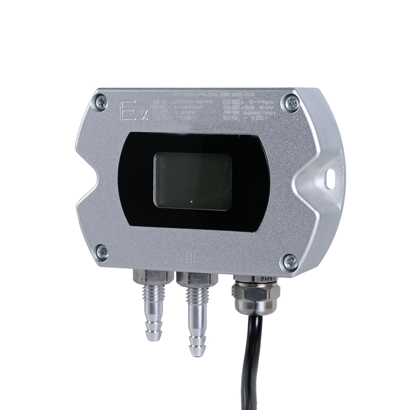
Translating datasheet specifications into field performance requires careful analysis. You must evaluate accuracy, materials, and safety certifications holistically. A specification sheet represents laboratory conditions; your evaluation must account for the reality of the plant floor.
Reference accuracy only tells part of the story. Manufacturers test reference accuracy in perfectly controlled laboratories at a stable 68°F. Installed accuracy reflects real-world performance. Temperature swings, static pressure, and mounting orientation degrade installed accuracy. Always calculate the Total Probable Error (TPE) for your specific field conditions. TPE combines reference accuracy, ambient temperature effects, and static pressure effects using a root-sum-square calculation.
Turndown ratio defines the transmitter's rangeability. A 100:1 turndown ratio means a transmitter with a 1000 inH2O upper range limit can be calibrated down to 10 inH2O. High turndown ratios allow you to standardize on fewer transmitter models. This reduces your spare parts inventory significantly. Instead of stocking ten different pressure ranges, you stock two models and configure them as needed.
Long-term stability dictates your maintenance schedule. Look for specifications guaranteeing stability as a percentage of the upper range limit over 10 years (e.g., ±0.15% of URL for 10 years). High stability reduces calibration frequency. It keeps your maintenance technicians focused on proactive tasks rather than routine zeroing.
Selecting the right wetted materials prevents catastrophic leaks. 316L Stainless Steel serves as the industry standard for general applications. Hastelloy C-276 provides excellent resistance to highly acidic or corrosive fluids, particularly those containing chlorides. Monel excels in hydrofluoric acid and saltwater environments. Tantalum offers supreme corrosion resistance but suffers from hydrogen permeation at high temperatures.
Hydrogen permeation occurs when monatomic hydrogen passes through the thin metal isolation diaphragm. Once inside, the atoms recombine into hydrogen gas molecules. This gas expands, causing the diaphragm to bulge outward and eventually rupture. If your process involves hydrogen ions, you must specify gold-plated diaphragms to block permeation.
You must also specify the internal fill fluid carefully. Standard silicone oil works for most processes. However, oxygen-rich environments require inert halocarbon fill fluids. If the isolation diaphragm ruptures, silicone oil reacting with pure oxygen causes violent combustion. High-temperature processes require specialized thermal fluids to prevent vaporization inside the sensor.
Combustible gases and dust create severe explosion risks. You must match the instrument certification to the area classification. Class I, Div 1 or Zone 1 environments require specialized protection methods to prevent the instrument's electrical circuits from igniting the atmosphere.
An explosion-proof differential pressure transmitter uses containment. Its heavy cast housing withstands an internal explosion. The housing features engineered flame paths. When an internal explosion occurs, the expanding hot gases are forced through these tight threaded paths, cooling the gas below the ignition temperature of the surrounding atmosphere before it escapes.
Intrinsically safe designs use energy limitation. They restrict the electrical energy entering the hazardous area via an intrinsic safety barrier in the control cabinet. Even under fault conditions, the circuit cannot generate a spark hot enough to ignite the gas. Safety Instrumented Systems (SIS) require devices with Safety Integrity Level (SIL 2 or SIL 3) certifications. These devices feature redundant internal diagnostics to guarantee fail-safe operation.
Even the most advanced transmitter fails if installed incorrectly. Physical piping, environmental exposure, and network integration dictate ultimate success. Field execution requires strict adherence to piping standards and environmental protection protocols.
Impulse piping causes more measurement errors than sensor failures. Trapped gas in liquid lines creates false head pressure. Trapped liquid in gas lines blocks the pressure signal. You must slope impulse lines correctly—typically a minimum of one inch per foot—to allow natural draining and venting. Gas service requires the transmitter mounted above the process tap so liquids drain back. Liquid service requires the transmitter mounted below the tap so gases vent back into the pipe.
Freezing in impulse piping destroys sensors. Water expanding into ice exerts thousands of pounds of pressure, crushing the isolation diaphragms instantly. You must heat-trace and insulate lines in cold climates. Environmental shielding protects the instrument housing. UV degradation destroys digital LCD displays rapidly. Direct sunlight bakes the electronics, causing severe temperature-induced zero drift. You must install instrument sun shades. Winterization enclosures protect transmitters from freezing rain and snow accumulation.
Proper valving ensures safe maintenance. 3-valve manifolds allow you to isolate the transmitter and equalize pressure across the sensor. You must operate them in a specific sequence: close the low-pressure block valve, open the equalizing valve, then close the high-pressure block valve. This prevents exposing one side of the sensor to full line pressure while the other is vented. 5-valve manifolds add dedicated vent valves. This allows technicians to bleed trapped pressure safely before removing the instrument for calibration.
Upgrading older facilities requires transitional planning. Integrating modern smart transmitters into legacy DCS or PLC architectures introduces protocol mismatches. Older control systems often only read analog 4-20mA signals. They ignore the valuable digital data riding on the wire.
Transitional design bridges this gap. You can utilize HART over legacy 4-20mA wiring. The control system reads the analog process variable for basic control. Meanwhile, a separate asset management system (AMS) strips the digital HART signal off the wire using a HART multiplexer. This allows phased plant upgrades. You gain modern digital diagnostics without ripping out legacy control cabinets or rewiring the entire facility.
Process control networks face growing cyber threats. Hackers target industrial infrastructure to disrupt operations. Hardwired 4-20mA loops are inherently secure from remote digital attacks, but modern digital protocols introduce risk. Wireless transmitters present a unique attack surface. You must secure WirelessHART and ISA100 networks meticulously.
Implement strong encryption keys. Rotate network join keys regularly. Segment your wireless sensor networks from the corporate IT network using industrial firewalls. Unauthorized access allows attackers to manipulate pressure readings. Falsified data causes control valves to open or close unexpectedly, leading to process instability, equipment damage, or hazardous spills.
Evaluating instrumentation requires looking past the initial purchase order. Long-term reliability and diagnostic capabilities drive the true value of the asset. A cheap instrument that fails frequently costs far more in labor and lost production than a premium instrument that runs flawlessly for a decade.
Purchasing commodity transmitters saves capital budget initially. However, these devices often drift faster. They require frequent recalibration. They fail sooner under harsh process conditions. Premium models feature advanced sensor designs, superior temperature compensation algorithms, and robust housings.
Extended calibration intervals offset higher initial capital expenditures. If a premium transmitter holds its calibration for five years, you save dozens of labor hours compared to a device requiring bi-annual checks. Reduced false trips keep the plant running. A single hour of prevented downtime often pays for the premium instrument multiple times over. When evaluating bids, factor in the expected maintenance labor over a ten-year operational window.
Modern transmitters act as process computers. They monitor their own health continuously. Advanced devices feature Statistical Process Monitoring (SPM). The transmitter learns the normal "noise" profile of your specific process. Plugged impulse line detection analyzes this signal noise. If a line begins to clog with process sludge, the noise profile flattens. The transmitter alerts you that the piping is clogging before the actual pressure reading deviates, allowing you to schedule maintenance during a planned outage.
Loop integrity monitoring detects wiring degradation, moisture in the terminal block, and ground faults before the signal drops completely. Decoding diagnostic alerts streamlines maintenance. Modern transmitters use standardized error codes, such as NAMUR NE 107. These codes instantly categorize faults into four distinct buckets: Failure, Out of Specification, Maintenance Required, and Function Check. This eliminates the guesswork of generic loop errors. Technicians know exactly what tools to bring before they leave the shop.
The manufacturer's support ecosystem matters immensely. Hardware fails eventually. When it does, you need rapid solutions. Evaluate the vendor's technical support responsiveness and local engineering presence.
Rapid access to replacement parts minimizes downtime. Check if the vendor maintains local inventory for critical wetted materials and specific pressure ranges. Lifecycle management portals help you track device revisions, download calibration certificates, and manage firmware updates. A strong vendor relationship ensures you have engineering support when designing complex remote seal systems or troubleshooting difficult flow applications.
Take the following actions to improve your measurement reliability:
Audit your current measurement loops to identify instruments with high calibration failure rates or frequent zero-drift issues.
Consult with instrumentation engineers to define precise static pressure, ambient temperature extremes, and chemical compatibility requirements for your worst-case process conditions.
Standardize your procurement specifications around NAMUR NE 107 diagnostic capabilities to streamline future troubleshooting and reduce maintenance labor.
Install sun shades, winterization enclosures, and correct impulse line sloping on all existing problematic installations to eliminate environmentally induced errors.
Implement a phased upgrade plan using HART multiplexers to extract digital diagnostic data from existing analog control loops.
A: Inaccuracies stem from several field issues. Trapped gas in liquid impulse lines or trapped liquid in gas lines distorts the pressure signal. Extreme ambient temperature swings cause zero drift. Leaking manifold valves prevent proper pressure equalization. Finally, physical damage to the isolation diaphragm from process spikes ruins calibration.
A: Calibration frequency depends on the manufacturer's long-term stability specification and your process criticality. Modern smart transmitters often maintain accuracy for 5 to 10 years. However, highly regulated industries or severe service applications may require annual verification. Always follow your internal quality control procedures.
A: No. Installing a standard transmitter in a classified hazardous area violates safety codes and creates a severe explosion risk. You must use a device certified for the specific area classification, utilizing either explosion-proof containment housings or intrinsically safe electrical designs.
A: A 5-valve manifold allows safe isolation, equalization, and venting. It includes two block valves to isolate the process, one equalizing valve to balance pressure across the sensor, and two vent valves. The vent valves allow technicians to bleed off trapped pressurized fluid safely before removing the instrument.
A: Turndown ratio indicates how much you can adjust the transmitter's measuring range. A high turndown ratio allows a single transmitter model to cover a wide variety of pressure ranges across your plant. This flexibility drastically reduces the number of spare transmitters you must keep in inventory.
A: Remote seals replace traditional impulse piping with flexible, fluid-filled capillaries. The process pressure pushes against a flush diaphragm at the pipe connection. This force transmits through the capillary fluid directly to the transmitter sensor. They prevent highly viscous, corrosive, or freezing fluids from clogging traditional impulse lines.


